Laundry Management System Entity Relationship Diagram
Introduction
Table of Contents
Efficient data management is vital in any service-based industry, and the laundry business is no exception. Whether it’s a small neighborhood laundromat or a large commercial laundry service, tracking customers, services, orders, payments, and employee activities requires an organized data system. That’s where a well-designed database comes in—and at the heart of database design lies the Entity Relationship Diagram (ERD).
An ER Diagram is a visual blueprint that outlines the entities in a system and the relationships between them. It plays a crucial role in designing structured, scalable, and logical databases. For a Laundry Management System, an ERD helps simplify complex processes like managing customer records, tracking laundry items, assigning delivery personnel, and handling payments.
The goal of this post is to guide you through the creation of an ER Diagram tailored specifically for a Laundry Management System. Whether you’re a database designer, software developer, IT student, or academic researcher, this post will help you visualize and structure the key data elements of the domain.
By the end, you’ll understand how to identify core entities, define attributes, build meaningful relationships, and apply best practices to create an efficient data model. Let’s break down the laundry business from a data perspective and build a database model that can power a modern, automated laundry management system.
Overview of the Domain
A Laundry Management System handles the end-to-end process of laundry services. Its core components include customers, service orders, laundry items, employees, pricing, delivery, and payment tracking.
Customers bring in their clothes or schedule a pickup. Each laundry order is categorized by service type—washing, dry cleaning, ironing, or folding. These orders are tagged, logged, and passed through various stages—collection, processing, quality check, and delivery. Employees or laundry attendants are assigned to handle specific tasks. Once the services are completed, invoices are generated, and customers can pay either online or on delivery.
Data management in this domain can become challenging without a structured system. Tracking individual clothing items, assigning services, managing repeat customers, and ensuring on-time delivery requires careful data organization. Mistakes in handling orders or customer records can result in lost clothes, incorrect billing, or dissatisfied customers.
Consider a small laundry business that processes 50+ customer orders daily. Without an organized database, managing those orders, tracking payment status, and coordinating delivery would quickly become chaotic.
That’s why ER Diagrams are essential—they provide a bird’s-eye view of the entire system and help in building a robust backend. The ERD not only simplifies the initial database design but also supports future expansion—like adding loyalty programs, mobile app integration, or inventory systems. By mapping out the structure beforehand, developers and stakeholders can build a data-driven laundry management solution that is efficient and reliable.
Key Concepts of ER Diagrams
To design a Laundry Management System database, you need to understand the building blocks of an Entity Relationship Diagram (ERD). These include entities, attributes, relationships, and keys.
- Entities represent real-world objects such as Customer, Order, Service, Employee, and Payment.
- Attributes describe the properties of each entity. For instance, a Customer has a Name, Contact Number, and Address.
- Relationships define how entities interact. For example, a Customer places an Order, and an Order includes one or more Laundry Items.
- Primary Keys (PK) uniquely identify each record in a table.
- Foreign Keys (FK) establish relationships between tables.
In the context of a Laundry Management System:
- A Customer places multiple Orders.
- Each Order includes one or more Items, such as clothes or garments.
- Services are applied to these items (e.g., washing, dry cleaning).
- Employees handle specific orders.
- Payments are linked to orders and track payment status.
Here’s a basic illustration:
Entity: Customer
- CustomerID (PK)
- Name
- Phone
- Address

Entity: Order
- OrderID (PK)
- Date
- Status
- CustomerID (FK)
Understanding these basics helps you design scalable, consistent, and efficient data models. Let’s now walk through the steps of building a full ER Diagram for a Laundry Management System.
Designing the ER Diagram for Laundry Management System
Step 1: Identify Entities
Start by identifying the core entities of the laundry management domain:
- Customer
- Order
- LaundryItem
- Service
- Employee
- Payment
- Delivery
Step 2: Define Attributes
Next, assign attributes to each entity:
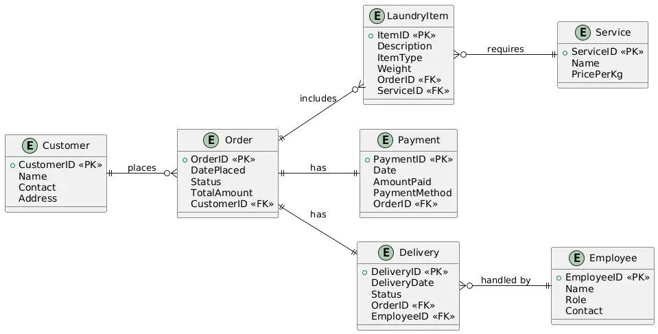
- Customer: CustomerID (PK), Name, Contact, Address
- Order: OrderID (PK), DatePlaced, Status, TotalAmount, CustomerID (FK)
- LaundryItem: ItemID (PK), Description, ItemType, Weight, OrderID (FK), ServiceID (FK)
- Service: ServiceID (PK), Name, PricePerKg
- Employee: EmployeeID (PK), Name, Role, Contact
- Payment: PaymentID (PK), Date, AmountPaid, PaymentMethod, OrderID (FK)
- Delivery: DeliveryID (PK), DeliveryDate, Status, OrderID (FK), EmployeeID (FK)
Step 3: Establish Relationships
- A Customer places one or more Orders.
- An Order contains one or more LaundryItems.
- Each LaundryItem is associated with a Service.
- An Employee is assigned to handle the Delivery of an Order.
- An Order has one Payment.
- A Delivery is linked to a specific Order.
Step 4: Specify Constraints
- Primary keys uniquely identify each record.
- Foreign keys enforce referential integrity.
- One-to-many relationships: One Customer to many Orders.
- Many-to-one relationships: Many LaundryItems to one Order.
Textual Summary
The ER Diagram begins with a Customer who creates Orders. Each Order has associated LaundryItems and is serviced using specific Services. An Order also triggers a Payment and may require Delivery. Employees are tied to the Delivery entity to manage assignments.
This structure ensures all business processes are represented—from item intake to payment and delivery.
ER Diagram Example
Here’s a conceptual layout of the ER Diagram:
- Customer → places → Order
- Order → includes → LaundryItem
- LaundryItem → requires → Service
- Order → has → Payment
- Order → has → Delivery
- Delivery → handled by → Employee
Each relationship uses foreign keys to maintain data consistency. For instance, LaundryItem uses OrderID and ServiceID as FKs to connect with both entities. This setup ensures that items are traceable by service type and order number.
The ERD clearly outlines the workflow: Customers place orders, orders list laundry items, services are applied, and orders are paid and delivered. This hierarchy supports automation and operational efficiency in real-world laundry services.

PlantUML Script for Laundry Management System ERD
@startuml
entity Customer {
+CustomerID <<PK>>
Name
Contact
Address
}

entity Order {
+OrderID <<PK>>
DatePlaced
Status
TotalAmount
CustomerID <<FK>>
}

entity LaundryItem {
+ItemID <<PK>>
Description
ItemType
Weight
OrderID <<FK>>
ServiceID <<FK>>
}

entity Service {
+ServiceID <<PK>>
Name
PricePerKg
}

entity Employee {
+EmployeeID <<PK>>
Name
Role
Contact
}

entity Payment {
+PaymentID <<PK>>
Date
AmountPaid
PaymentMethod
OrderID <<FK>>
}

entity Delivery {
+DeliveryID <<PK>>
DeliveryDate
Status
OrderID <<FK>>
EmployeeID <<FK>>
}

Customer ||--o{ Order : "places"
Order ||--o{ LaundryItem : "includes"
LaundryItem }o--|| Service : "requires"
Order ||--|| Payment : "has"
Order ||--|| Delivery : "has"
Delivery }o--|| Employee : "handled by"
@enduml
Best Practices for Laundry Management ER Diagrams
To design an effective Laundry Management System ER Diagram, follow these best practices:
- Normalize your data: Ensure no redundant or repeating fields by applying normalization principles. This keeps the database clean and efficient.
- Keep it scalable: Anticipate future features such as loyalty programs or inventory tracking, and design the schema to support growth.
- Use clear naming conventions: Entity and attribute names should reflect their real-world counterparts for better clarity.
- Define all keys explicitly: Specify primary and foreign keys to maintain data integrity.
- Avoid overcomplicating: Too many relationships or entities can make the ERD hard to understand. Keep it functional and simple.
Tools to use:
- Lucidchart
- Draw.io
- ERDPlus
- MySQL Workbench
Each offers drag-and-drop interfaces that simplify ERD creation and export.
Real-World Applications
A Laundry Management System ER Diagram translates directly into a functional database schema. It supports software systems used in laundromats, dry cleaners, and commercial laundry services.
These systems rely on ERDs to manage daily operations—order tracking, employee scheduling, billing, and delivery coordination. SaaS solutions like CleanCloud or LaundroKart use similar data models behind the scenes.
Industries such as hospitality, healthcare, and garment manufacturing often require integrated laundry services. A well-structured ERD allows for tailored databases that meet these industry-specific needs.
Conclusion
Designing an ER Diagram for a Laundry Management System helps you visualize and structure the key components of the domain. From customers and orders to services and payments, every element is mapped and connected.
This post walked you through the essential steps—identifying entities, defining attributes, creating relationships, and building a complete model. With this knowledge, you can confidently build or improve any laundry management software’s backend system.
Now it’s your turn. Try creating your own ERD using the principles shared here. Explore how different laundry businesses might add unique entities like coupons or inventory.
Got feedback or questions? Drop them in the comments. Stay tuned for the next post where we’ll explore ERDs for Hospital Management Systems or Booking Applications.
You may visit our Facebook page for more information, inquiries, and comments. Please subscribe also to our YouTube Channel to receive free capstone projects resources and computer programming tutorials.
Hire our team to do the project.