Waste Management with Reward System ER Diagram
This article will walk you through the process of creating an entity relationship diagram, often known as an ERD, for the project entitled Waste Management with Reward System.
Waste Management with Reward System Description
The purpose of this project is to develop a waste management system that encourages people to recycle more. The system will include a rewards program in which people can earn points for recycling. These points can be redeemed for rewards such as discounts at local businesses or gift cards.
The system will work as follows:
- People will earn points for recycling.
- People can use their points to redeem rewards.
- The system will help motivate people to recycle more by providing them with rewards for doing so.
The benefits of this system are that it will increase the amount of recycling done in society, it will be cost effective, and it will be easy to use.
One of the biggest challenges with this system will be motivating people to recycle more. It may be difficult for people to earn points for recycling if they do not think that it is worth it. The rewards program could help to motivate people by offering them a discount on their purchases or a gift card.
Please visit the link below for more information about the project.
ERD
This is the first phase of the development of the Waste Management with Reward System, which will eventually be used as the basis for the production of the actual database that will be used by the system.
We will develop an entity relationship diagram for the Waste Management with Reward System and describe the steps involved in creating the diagram.
Let us begin with the symbols that are used in the ER Diagram.
The rectangle shape represents the entity that is being shown in the diagram below. At some point in the future, we will use this entity to make a database table for our Waste Management with Reward System.
The shape of a diamond can show how a relationship works, like how it fits together. A lot will depend on this. A primary key to foreign keys relationship is often the best way to do this.
The shape of the oval is a way to show the attribute for the entities specified. Columns or fields will be added to each table in the Waste Management with Reward System, and this will be the case.
We will follow the 3 basic rules in creating the ER Diagram.
- Identify all the entities.
- Identify the relationship between entities and
- Add meaningful attributes to our entities.
Step 1. In the Waste Management with Reward System we have the following entities:
- User
- User Group
- Member
- Junkshop
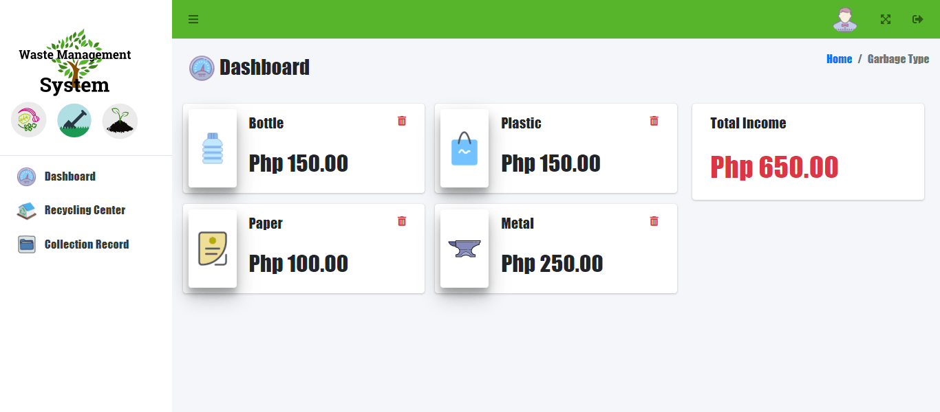
- Garbage Type
- Collection Record
The Waste Management with Reward System, according to our model, consists of six components or entities, which are mentioned above. The tables that make up our database tables, which we will design and develop as we design and construct the Waste Management with Reward System database schema, will be the components that make up these pieces.
To explain how the entire system works, we’ll draw a rectangle with the Waste Management with Reward System components within. The different entities and items that make up the Waste Management with Reward System are depicted in the diagram below.
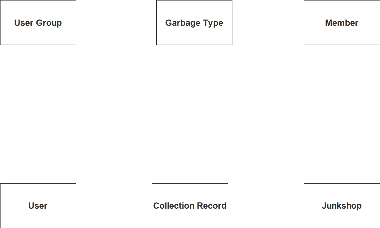
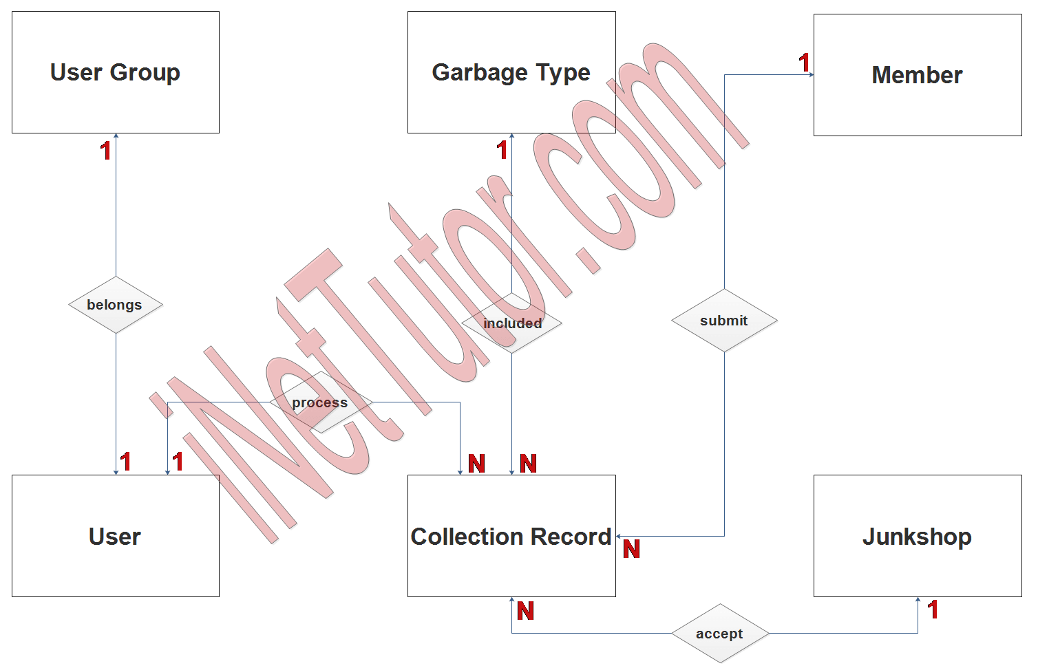
Step 2. After we have specified our entities, it is time now to connect or establish a relationship among the entities.
- User account belongs only to one (1) user group or category (1 to 1 relationship).
- User can process multiple transactions on the collection and record keeping of the information submitted by the members. These are the list of recyclable materials to be turnover to the junkshop (1 to many relationship).
- List of garbage are group according to their type and is being included or encoded in the collection record (1 to many relationship).
- A member of the project can encode the list of garbage or recyclable materials as indicated in the system and turnover it to the nearest junkshop to claim their rewards (1 to many relationship).
- The junkshop can keep track of the records through the collection record module of the project (1 to many relationship).
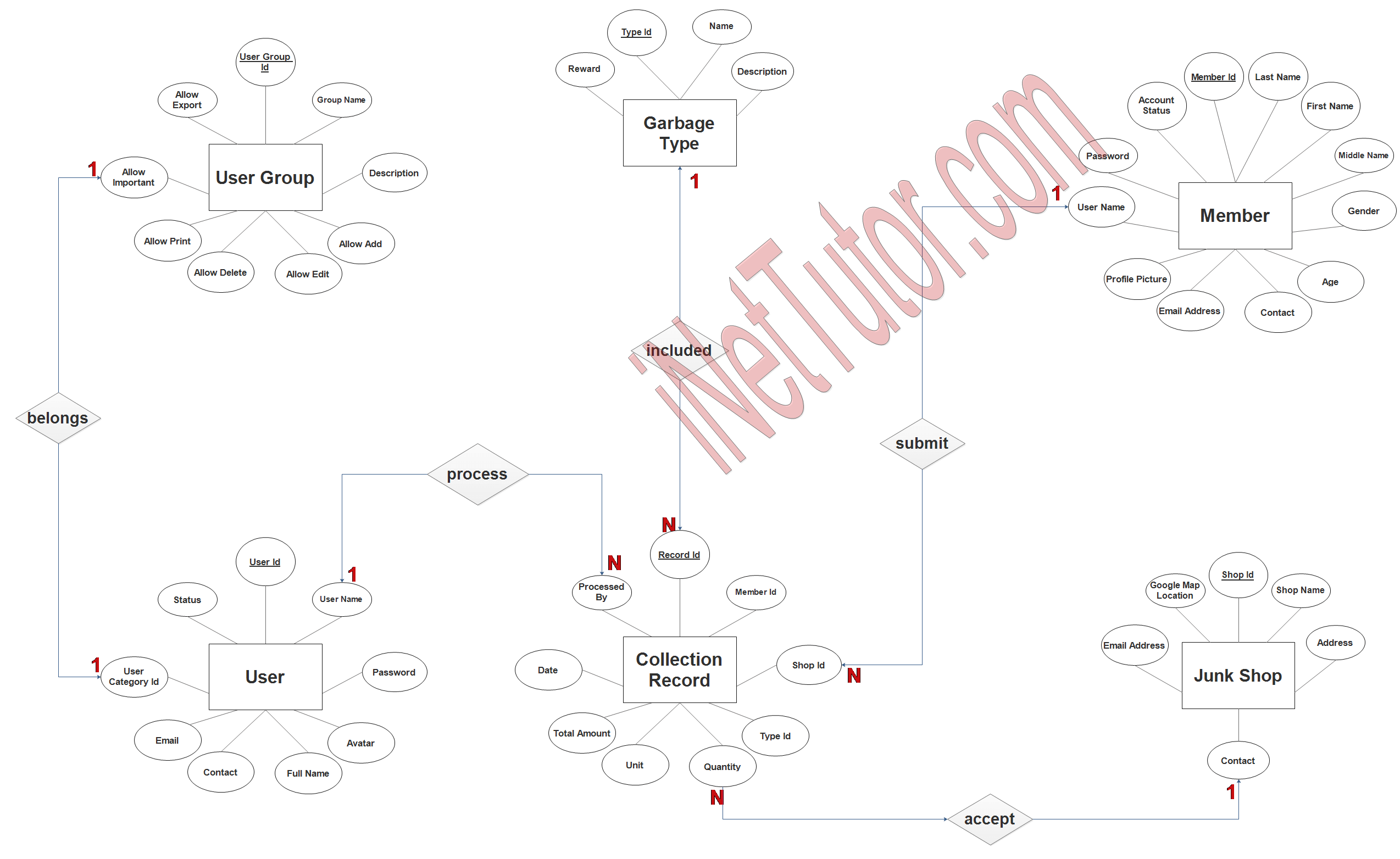
Step 3. The last part of the ERD process is to add attributes to our entities.
User Entity has the following attributes:
- User_ID – primary key represented with underline
- Username
- Password
- Avatar
- Fullname
- Contact
- User category ID – foreign key
- status
User Group Entity has the following attributes:
- User group ID
- Group name
- Description
- Allow add
- Allow edit
- Allow delete
- Allow print
- Allow import
- Allow export
Member Entity has the following attributes:
- Member ID – primary key represented with underline
- Last name
- First name
- Middle name
- Gender
- Age
- Contact
- Email address
- Profile picture
- Username
- Password
- Account status
Junkshop Entity has the following attributes:
- Shop ID – primary key represented with underline
- Shop name
- Address
- Contact
- Email address
- Google map location
Garbage Type Entity has the following attributes:
- Type ID – primary key represented with underline
- Name
- Description
- Reward
Collection Record Entity has the following attributes:
- Record ID – primary key represented with underline
- Member ID – foreign key
- Shop ID – foreign key
- Type ID – foreign key
- Quantity
- Unit
- Total amount
- Date
- Processed by (user_id) – foreign key
Summary
Waste management is critical since it aids in the preservation of a clean and safe environment. People will be rewarded for their efforts, so introducing a waste management with reward system will help to enhance overall waste management practices. This will inspire individuals to be more environmentally conscious and recycle more. People will be rewarded for their efforts, and the environment will be cleaner and safer as a result. In order to improve overall waste management practices, a waste management with reward system is very necessary and should be adopted.
Entity Relationship Diagram (ERD) is a graphical representation of entities and their relationships. ERD is used in software development to model the data structures of a system.
Entity Relationship Diagram is used to:
- Model the data structures of a system.
- Represent the relationships between entities.
- Aid in the design and maintenance of a system.
- Define the problem domain for a system.
- Compare different models of a system.
ERD is used to model the data structures of a system by specifying how the entities are related to each other and what data they contain. ERD can also be used to represent the relationships between entities. This information can be used to help design and maintain a system. Lastly, ERD can be used to define the problem domain for a system. By doing this, it is easier for developers to understand the structure of the data and how it relates to other parts of the system.
In addition, we will also give you a PowerPoint or Video Presentation for the entire ER Diagram. Make sure you visit and subscribe to our YouTube channel to see the videos.
You may visit our Facebook page for more information, inquiries, and comments. Please subscribe also to our YouTube Channel to receive free capstone projects resources and computer programming tutorials.
Hire our team to do the project.
Related Links and Articles:
Waste Management with Reward System
Online E-Waste Management System Capstone Proposal
Jewelry Sales Accounting and Appraisal System Free Download PHP Template
Mobile Based Tuition Fee Payment App using Dragon Pay API
Barcode Based Document Control and Management System
Related Literature on NPK Soil Content Archiving Application
